Tubing Wall Thickness Selection
Tubing Wall Thickness Selection
Written By: Brian Aplin, Field Engineer | September 2019
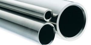
Selecting tubing for your fluid system can be fairly trivial. Ensuring that the tubing material and wall thickness are compatible with the system parameters could be the only factors in making the determination between ¼" x 0.035" Stainless Steel or Copper of the same dimensions. However, for systems where pressure, flow, and phase are of concern, system designers should consider wall thickness further.
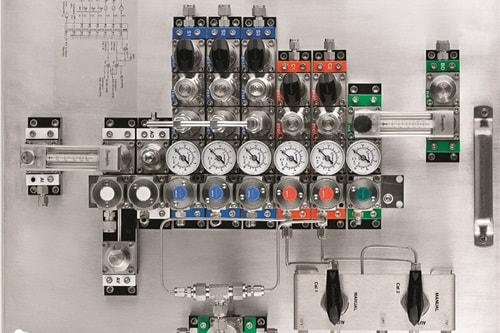
In analytical instrumentation systems where there is a requirement to take a sample of the process to an online or offline analyzer, system designers should consider pressure decay across the transport line to the sample conditioning system, and then again across the sample return or disposal system. Without enough motive force to move the fluid, the system may end in a no-flow situation, or move the fluid so slowly that it fractionates or changes phases, producing a sample that is no longer representative of the process.
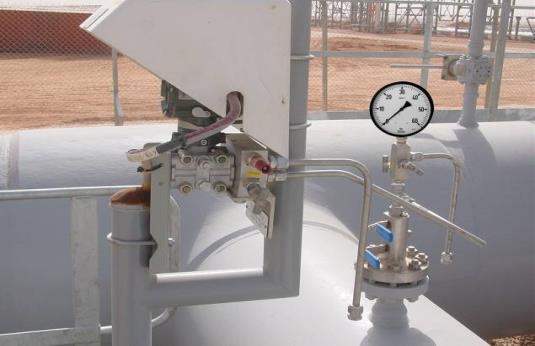
For process instrumentation and control systems, the same considerations must be investigated for similar reasons. Not only because the pressure could drop in an extended impulse or transport line, but when the phase of the fluid is changed, an accurate physical reading such as pressure or flow cannot be obtained, which in turn controls the process incorrectly leading to an unusable product.
Calculations for pressure drop, flow regime, and phase should be performed before finalization of tubing size selection. In many cases, thicker wall tubing may be required in order to maintain turbulent flow in the transport lines; however, this may also cause too great a pressure drop compared to the available pressure differential or cause volatile liquids to bubble. These decisions should be made by the system owner and designer using sound engineering practices.
Density and viscosity of the system fluid are required in order to calculate pressure loss in the tubing. These values should be calculated at the actual tubing temperatures and pressures. After these values are obtained, applying the Darcy Equation will estimate the pressure drop.
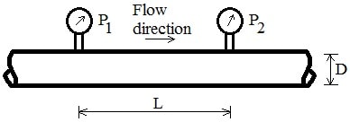
The Darcy Equation: ∆P=(f*L*ρ*u^2)/2D where ∆P is the pressure drop, f is the friction factor of the tubing, L is the length of the tubing, ρ is the density of the system fluid, u is the fluid velocity (u=L/t), and D is the inside diameter of the tubing chosen.
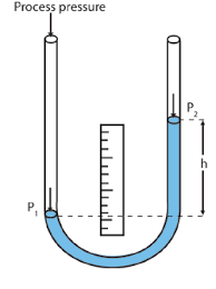
The Darcy equation will account for pressure drop in horizontal lines when the system fluid is a liquid, and there exists an elevation change. Accounting for this static head gain or loss can be obtained by using the following equation: ∆P=h*ρ*g, where h is the elevation change and g, is the gravitational constant.
Waters, "Industrial Sampling Systems Reliable Design and Maintenance for Process Analyzers" pp. 84-120
For more information on this, reach out to our Field Engineering team or pick up your own copy of Tony Waters' "Industrial Sampling Systems Reliable Design and Maintenance for Process Analyzers."